Shut-off and regulating valves for hydro power plants, thermal power plants and industrial systems — engineered to the hydraulic data of each project and delivered with full calculation and test documentation.
DN 100–4000PN 6–160Heads to 1000 mHydraulic or electric actuationEN 10204 3.1 / 3.2 certificates
Hydro power
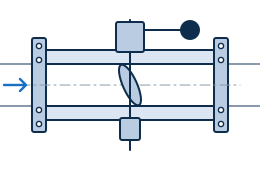
Turbine inlet butterfly valves
Absperrklappe · Leptirasti zatvarač
The main shut-off element between the penstock and the turbine. The valve holds full static pressure with the unit stopped, closes safely against flow in an emergency, and is opened only after the pressure across the disc has been balanced through the bypass.
Bodies are welded from fine-grain structural steel or cast, with a lens or lattice disc, self-lubricating bearings and a replaceable seat. Standard actuation is a hydraulic servomotor with a counterweight, so that closing is completed by gravity even with a total loss of oil pressure and power.
Technical data — typical range
Nominal size
DN 500 – 4000
Pressure rating
PN 6 – 25, higher on request
Design head
up to 250 m
Body
Welded S355J2+N or cast steel; flanged or weld ends to EN 1092-1
Disc
Lens or lattice type, welded steel, stainless steel sealing face
Double-flanged butterfly valve with servomotor and counterweight
Hydro power
Spherical (ball) valves
Kugelschieber · Kuglasti (sferni) zatvarač
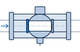
Where the head is too high for a butterfly valve, the spherical valve takes over. With the rotor open, the bore is fully clear: head loss is practically zero and the flow profile at the turbine inlet is undisturbed — decisive for Pelton and high-head Francis units.
Sealing is by a movable service seal, hydraulically pressed against the rotor, backed by an independent maintenance seal that allows work downstream with the penstock under pressure.
Technical data — typical range
Nominal size
DN 300 – 2500
Pressure rating
PN 16 – 250, higher on request
Design head
up to 1000 m
Body
Two- or three-piece, cast GS-20Mn5 or welded S355J2+N, fully machined
Rotor
Welded or cast steel, full bore, stainless steel sealing band
Sealing
Hydraulically operated service seal plus independent maintenance seal; hard-faced or ceramic-coated seats
Trunnions
Stainless steel trunnions in self-lubricating bearings, external adjustment
Actuation
Hydraulic servomotor with counterweight; emergency hand pump; overspeed closing
Equipment
Bypass system, seal control block, drainage, air valve, position indication, dismantling joint
Standards
EN 1074, DIN 19704, IEC 60308, EN 1092-1
Application
High-head turbine inlet, Pelton and Francis units, pumped-storage plants, penstock guard valve
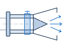
A fixed-cone dispersion valve discharges to atmosphere and converts the whole pressure head into a wide, aerated hollow jet. Energy is dissipated in the air rather than in the structure, so no downstream stilling equipment is loaded by a concentrated jet.
Flow is controlled by an external sliding sleeve, which keeps the seat out of the high-velocity zone. Where the discharge has to be contained, the valve is supplied with a fixed or adjustable hood.
Technical data — typical range
Nominal size
DN 300 – 3000
Pressure rating
PN 6 – 40
Design head
up to 200 m
Body and cone
Carbon steel with stainless steel overlay in the wetted zone, or fully stainless; fixed 45° cone on radial ribs
Closing element
External sliding sleeve, stainless steel guided, seat outside the high-velocity zone
Actuation
Two synchronised hydraulic cylinders or electric actuators; manual emergency operation
Options
Fixed or adjustable hood, energy dissipation chamber, aeration, downstream protection, position feedback
Standards
EN 1074, DIN 19704, EN 1092-1
Application
Dam bottom outlets, reservoir drawdown, compensation and environmental flow, turbine bypass, energy dissipation
Fixed-cone valve with external sliding sleeve
Hydro power · Water management
Plunger valves
Ringkolbenschieber · Prstenasti klipni zatvarač
A regulating valve for duties where the pressure drop is large and permanent. The axially moving plunger produces an almost linear flow characteristic and, in combination with a perforated or slotted trim, keeps cavitation inside the trim instead of on the body wall.
Because the seat is closed metal-to-metal outside the throttling zone, the valve regulates and shuts off with one element — throttling for years without loss of tightness.
Technical data — typical range
Nominal size
DN 150 – 2500
Pressure rating
PN 10 – 100
Body
Cast or welded steel, epoxy lined; stainless steel cladding in the throttling zone
Plunger and trim
Guided stainless steel plunger with perforated cylinder or slotted trim sized for the duty point
Seat
Replaceable stainless or hard-faced seat ring, metal-to-metal tight closing
Characteristic
Near-linear flow control, controlled cavitation, low noise and vibration
Actuation
Electric actuator with gearbox, hydraulic cylinder or manual gear; 4–20 mA position feedback
Standards
EN 1074-5, DIN 19704, EN 1092-1
Application
Flow and pressure regulation, turbine bypass, pressure reduction stations, reservoir outlets, water supply
Plunger valve with perforated trim and electric actuator
Thermal power
Gate valves
Absperrschieber · Ravni zasun
Shut-off valves for steam, feedwater, condensate and cooling water in thermal power plants and process industry. Supplied with a flexible wedge or as a parallel slide valve, with a bolted or pressure-seal bonnet according to the class.
Seating surfaces are hard-faced with a cobalt-based alloy, which keeps them tight through repeated thermal cycles. Body and bonnet materials are selected for the design temperature, from carbon to creep-resistant low-alloy steel.
Technical data — typical range
Nominal size
DN 50 – 1200
Pressure rating
PN 16 – 160 / Class 150 – 900
Design temperature
up to 550 °C
Body and bonnet
P250GH, 16Mo3, 13CrMo4-5, 1.4571; bolted or pressure-seal bonnet
Closing element
Flexible wedge or parallel slide, guided in the body
Seats
Stellite hard-faced seating surfaces on body and wedge
Ends
Butt weld to EN 12627, or flanged to EN 1092-1 / ASME B16.5
Actuation
Handwheel, bevel gear or electric actuator; bypass and drain connections on request
Standards
EN 1984, EN 12516, EN 12266, EN 10204 3.1
Application
Main steam, feedwater and condensate lines, cooling and service water, process isolation
Wedge gate valve with bolted bonnet
Industry · Water supply
Check valves with hydraulic damping
Rückschlagklappe mit hydraulischer Dämpfung · Nepovratni zatvarač s hidrauličkim prigušenjem
On pump trip the column reverses and an undamped check valve slams shut, generating a pressure surge that the pipeline has to absorb. An external hydraulic damper takes control of the last part of the travel and removes the surge.
Damping is set in two stages — fast over the first part of the stroke, then slowed over the final closing — and both stages are adjustable on site with the plant running.
Technical data — typical range
Nominal size
DN 100 – 2000
Pressure rating
PN 10 – 40
Type
Swing or tilting-disc check valve, single or double eccentric, with external damping cylinder
Body
Cast or welded steel, ductile iron on request; epoxy coated
Disc and seat
Steel disc with EPDM / NBR or metal seat, stainless steel shaft in maintenance-free bearings
Damping
Two-stage hydraulic damper, fast closing 0–80 % and slow closing 80–100 %, both adjustable
Options
Counterweight lever, closing-time adjustment, position switches, air release
Standards
EN 1074-3, EN 12334, EN 1092-1
Application
Pump discharge lines, pumped-storage plants, cooling water systems, water supply and irrigation
Check valve with external two-stage damper
Engineered to order
Special and custom valves
A large part of our work is equipment that does not come from a catalogue: valves for non-standard heads and installation conditions, guard and bifurcation valves, aeration and drainage assemblies, and complete replacements for valves on plants that have been in operation for decades.
For a replacement we survey the existing installation, take the connecting dimensions from the plant, and design a new valve that fits the existing civil works and penstock — usually with a shorter outage than a modification of the structure would require.
Reverse engineering
Measurement of the installed valve, material identification, recalculation and new drawings.
Fit to existing works
Face-to-face dimension, anchoring and controls matched to the plant so that civil works stay untouched.
Hydraulic study
Closing-time and surge analysis, cavitation check, sizing of the actuation and the oil unit.
Spare parts and service
Seals, seat rings, bearings, shafts and complete overhaul of valves in operation.
Designed to the project's data, not to a catalogue
All figures on this page are typical ranges for orientation. Larger sizes, higher pressure ratings, special materials and special designs are available on request — please state the head, flow, medium, temperature and required closing time with your enquiry.
Have a technical enquiry?
Send us the head, flow, nominal size and operating regime and you will receive a technical proposal with a preliminary price.